The Design for Manufacture and assembly (DFMA) process is utilised in all forms of manufacturing. Errors made early in the design process when designing a component or a system of components can cause significant problems further down the value chain. If the appropriate consideration is not given to key design criteria with respect to manufacturing and assembly then companies could end up paying the price at a later stage.
An example of this would be a recall on a defective component in a car. In this example, the car manufacturer must incur the cost of redesigning the replacement parts, supply the replacement parts, pay an authorised dealership to have a mechanic replace the defective parts and, in some cases, provide a courtesy car – this will obviously lead to significant cost for the manufacturer as well as irreversible reputational damage.
PEM/ BESPRA Collaboration
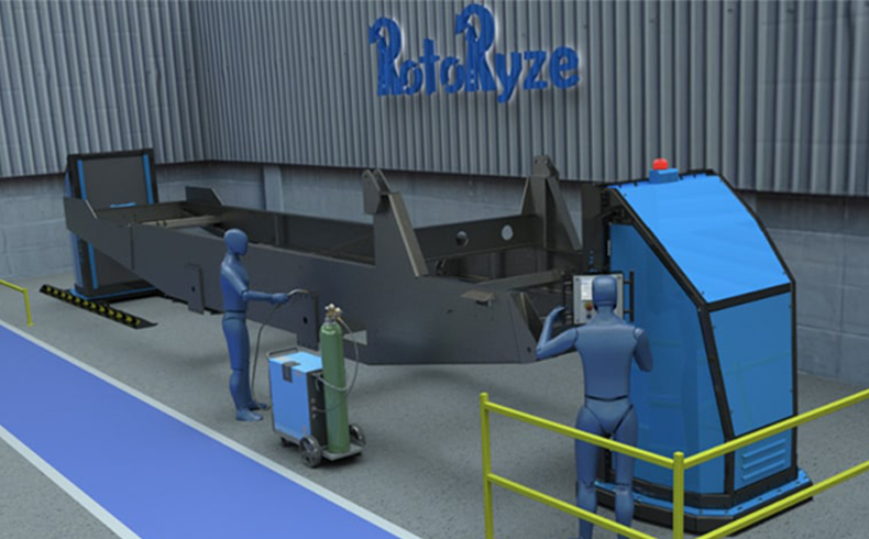
The PEM Technology Gateway have recently completed a cross-border collaboration in the DFMA space with metal fabrication company BESPRA. The company’s main object was to develop their own heavy duty welding positioner (RotoRyze), with the intention of mass manufacturing the system in the future. The system in question would be used to handle heavy duty workpieces while the company’s fabrication team were working on them. As well as the need to be of solid structural design, the positioner also needed to have automation incorporated into it to allow the fabrication team to alter the position of workpieces for accessibility and ergonomics.
For more information on this product please visit the BESPRA website.
The DFMA Process
Like any other design processes, DFMA follows a set of predetermined steps, some of which are iterative in nature. However, to avoid any issues later in the products lifecycle, a specialist knowledge of the associated engineering field and related manufacturing techniques is essential. The key DFMA process steps include but are not limited to:
Define the problem and establish objectives: Speak to all the key stakeholders in order to gain more insight about problem. The stakeholders include: the MD, engineering staff, technical staff, the end user, and 3rd party manufacturers. The idea here is that each stakeholder can provide input from a unique perspective that other stakeholders could potentially miss.
Create a User Requirement Specifications (URS) for the product: The URS is used to define what the “end user” needs to get from the product under development. The URS should take in to account the whole continuum of concerns, from the initial concept idea to packaging and delivery. Time spent developing a robust user requirement specification will help avoid problems or oversights with the product later in the product lifecycle.
Concept generation and selection:
Concept generation is a five-step methodology for producing valid subsystems and components. These five steps include:
1. Clarifying the problem – This involves taking a closer look at key inputs and decomposing complex problems into simpler sub-problems.
2. Searching externally – Question users and consult experts. Research published literature, search for any existing patents and benchmark related products on the market.
3. Searching internally – Leverage existing staff knowledge to generate initial concept solutions. Many ideas should be generated here in a non-judgemental way, even ideas that may not seem viable.
4. Exploring systematically – This looks at all the potential combinations of solutions for each subsystem. This can be achieved using:
- Concept fragments
- Concept classification trees
- Problem decomposition models
- Concept combination tables
5. Reflecting on the solutions and the process – This should be done throughout the whole process to ensure that as many solutions are captured as possible.
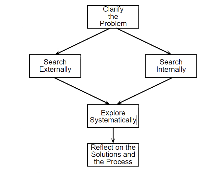
Figure 2 – Concept Generation Flow Chart
Concept selection is an iterative process which ultimately leads to a single concept design upon which subsequent development activities will be focused. Methods for choosing a concept include:
- External decision
- Product champion
- Intuition
- Pros vs cons
- Prototyping and testing
- Decision matrices
The decision matrices method offers several benefits such as documenting the entire decision-making process and ensuring that a competitive design will be selected. There are two key decision matrices that assist with selecting the optimum concept:
- Concept Screening – Is the initial screening process used to screen out non-viable ideas. This is achieved by rating and ranking each concept. Each concept is either accepted, eliminated, combined or revised based on the outcome of the initial rating and ranking process.
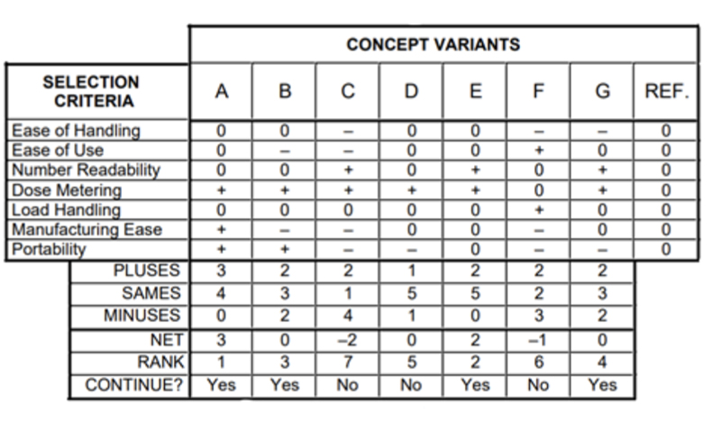
Table 1 – Concept Screening Matrix Example
2. Concept Scoring – Is a more refined process which uses weighted scoring to evaluate key selection criteria for each of the concepts that made it through the initial screening process. Each is rated and ranked, with the highest scoring concept moving forward for development.
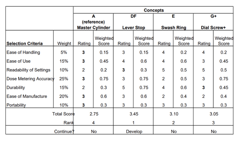
Table 2 – Concept Scoring Matrix Example
Product Development Phase:
Develop the initial CAD models of the entire system, its sub-systems and its components while considering material requirements, manufacturability, off-the-shelf components, cost estimates and potential supply chains.
Execute experimental loading of critical components utilising CAD simulation analysis (FEA). Evaluate the results of all key structural components and modify the design as required to achieve the target load rating for the overall system. The target load rating for the welding positioner was 5 ton and included a factor of safety (FOS) of 5.
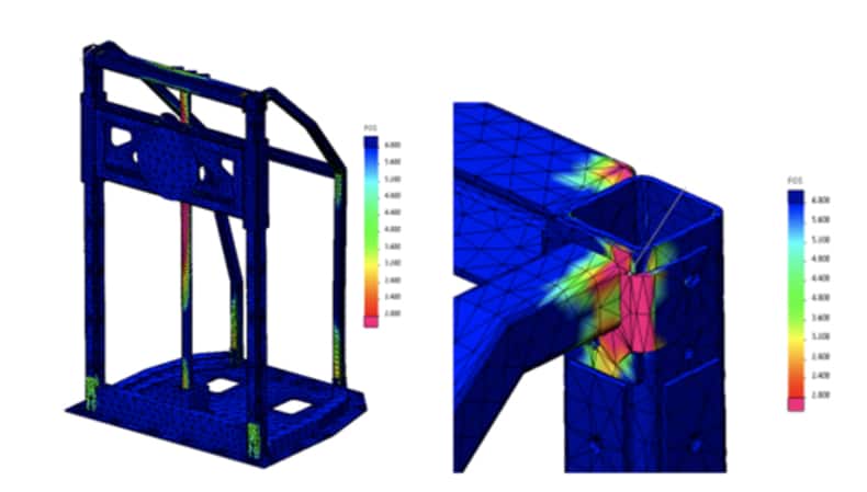
Figure 3 Initial FEA simulation results on the positioners frame subassembly
Detailed design phase:
Where necessary, amend the CAD models by applying the learnings from the product development phase – it is important here to once more consider manufacturing and assembly considerations before finalising the design as this can save time redesigning components or subsystems at a later stage. Identify various material and off-the-shelf component requirements to manufacture the system and undertake a value engineering exercise to review the value for money of the final design. Conduct a hazard and safety evaluation analysis to ensure that all health and safety concerns are captured and mitigated against. Finally, create working drawings and write the final specifications for the system.
Manufacture, assembly and testing of prototypes:
Begin the process of manufacturing and assembling the beta prototype based on the detailed design drawing. Once the design has been complete, execute physical load testing on the prototypes key performance attributes to confirm that the system performs as per the URS. Execute extensive field trials with involvement of key stakeholders and request feedback on the systems performance and ergonomics. Review the feedback provided and, if necessary, implementation any potential improvements to the design.
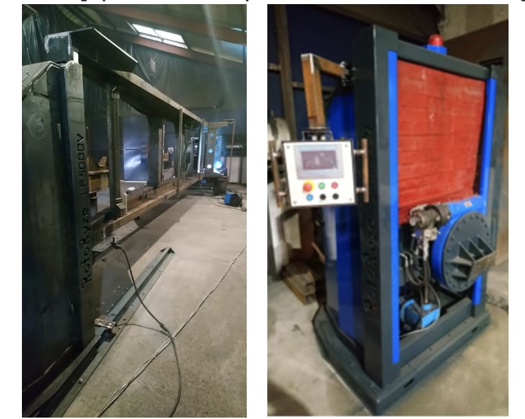
Figure 4 – Manufacturing of the Beta Prototype
Why use PEM Technology Gateway?
Researchers in the PEM Technology Gateway can provide technical engineering solutions that allow companies to develop new products, processes, or services right across the full product lifecycle, with specialisation in design for manufacture (DFMA) in precision engineering and manufacturing sectors.
If you would like to learn more or speak to a PEM Technology Gateway researcher, please contact cliodhna.carroll@atu.ie.
